555 Timer Circuit Schematic / Analysis of 555-Based PWM Circuit | Math Encounters Blog / • the 555 timer circuit should already be built but if not, assemble it as shown in fig.
byAdmin-
0
555 Timer Circuit Schematic / Analysis of 555-Based PWM Circuit | Math Encounters Blog / • the 555 timer circuit should already be built but if not, assemble it as shown in fig.. It is a affordable, stable and user friendly ic in application such as monostable and bi stable. 555 timer was first introduced by signetics corporation in 1971 as se555/ne555. 555 ic automatically switches back to stable state after some time, this time, for which the 555 stays in quasi stable state, is determined by the time constant of rc network in the circuit. Monostable 555 timer circuits will automatically trigger and start a timing cycle when power is applied to the circuit. The 555 timer, designed by hans camenzind in 1971.
One configuration of this timer creates a perfect square wave. The circuit layout is for a 555 timer in astable mode. Clap switch circuit using ic 555 timer & without timer. • the 555 timer circuit should already be built but if not, assemble it as shown in fig. Basically, this means that you will have a continuous transition from a high voltage level (determined by and slightly less than your supply voltage) to 0v at a certain frequency (number of times per second).
Simple Time Delay Circuit using 555 Timer - ArRoboticsBlog from circuitdigest.com We can see that it us made up of 21 transistors, 4 diodes, and 15. The circuit inside the 555 is just an amplifier with 2 inputs and an output. Monostable 555 timer circuits will automatically trigger and start a timing cycle when power is applied to the circuit. And now a full schematic of the 555 timer oscillator with single step and free run option. The schematic is shown in fig 5. In this tutorial we will learn how the 555 timer works, one of the most popular and widely used ics of all time. The breadboard schematic of the above circuit is shown below. A 555 timer is a very versatile.
These are easy to build 555 circuits for beginners and advanced engineers.
Clap switch circuit using ic 555 timer & without timer. Si notation all the schematics in this ebook have. This bistable configuration does not use any rc timing. This 555 timer is in astable mode. This cycles 60 times every second. The lm555 has a maximum typical supply voltage rating of 16v while the relay's armature coil is enabled at 12v. The 555 timer can provide time delays ranging from several minutes for one cycle of operation to many thousands of cycles per second. Here is the list of 40 555 timer circuits that can help you in understanding 555 timer functions.first five circuits explains. This is the schematic below for the 555 timer that creates one square wave output. To make the same circuit as mentioned above without ic 555 timer, we will have to use the following basic electronic components and devices. It is a affordable, stable and user friendly ic in application such as monostable and bi stable. The 555 timer, designed by hans camenzind in 1971. • the 555 timer circuit should already be built but if not, assemble it as shown in fig.
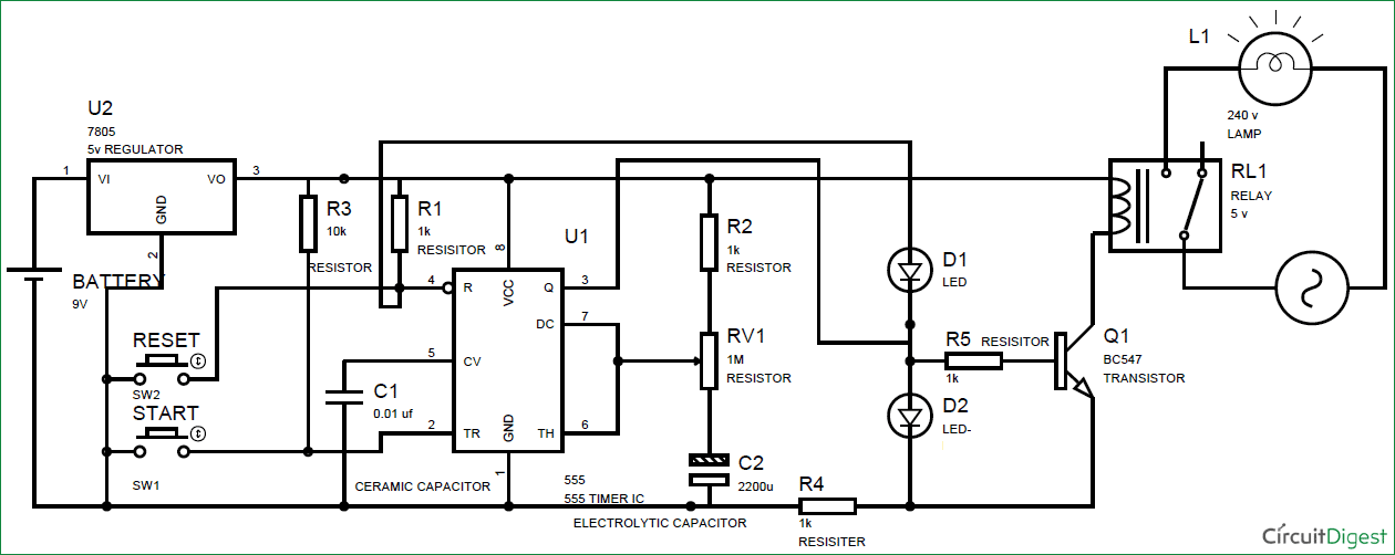
To observe the 555 timer in astable mode, let's build a circuit that uses the 555 timer's oscillating output to make. The 555 timer is a simple integrated circuit that can be used to make many different electronic circuits. The 555 timer is an integrated circuit, it is extremely versatile and can be used to build lots of different circuits. Derivatives provide two (556) or four (558) timing circuits in one package. The timer generates an output pulse with an on time period determined by the rc network i.e t = 1.1rc.
Free Circuit Diagrams: Timer 555 Schematic from 3.bp.blogspot.com The timer generates an output pulse with an on time period determined by the rc network i.e t = 1.1rc. This is the schematic below for the 555 timer that creates one square wave output. The circuits explained here are 10 best small timer circuits using the versatile chip ic 555, which generates predetermined time intervals in response the image shown below represents the internal schematic of a standard ic 555. Here is the list of 40 555 timer circuits that can help you in understanding 555 timer functions.first five circuits explains. Basically, this means that you will have a continuous transition from a high voltage level (determined by and slightly less than your supply voltage) to 0v at a certain frequency (number of times per second). The schematic is shown in fig 5. Due to its relative simplicity, ease of use and low cost it has been used in literally thousands of applications. Astable mode can produce digital square waveforms that go back and forth between.
The lm555 has a maximum typical supply voltage rating of 16v while the relay's armature coil is enabled at 12v.
One configuration of this timer creates a perfect square wave. The 555 and 7555 are called timers or timer chips. This cycles 60 times every second. Basically, this means that you will have a continuous transition from a high voltage level (determined by and slightly less than your supply voltage) to 0v at a certain frequency (number of times per second). Figure 10 shows a 555 square. In most cases you add a capacitor and resistor to produce a circuit known as a time delay circuit and the the 555 and 7555 are called timers or timer chips. The 555 timer, designed by hans camenzind in 1971. The schematic is shown in fig 5. Connect power and ground to pins 8 and 1 of the 555 timer (red and black wires). This bistable configuration does not use any rc timing. The timer's internal circuitry is largely responsible for this. Monostable 555 timer circuits will automatically trigger and start a timing cycle when power is applied to the circuit. It is a affordable, stable and user friendly ic in application such as monostable and bi stable.
A 555 timer is a very versatile. You can either follow the previous schematic or follow the breadboard wiring diagram below. Above schematic diagram shows the 555 timer monostable multivibrator circuit. You can watch the following video or read the written tutorial below. Look at the circuit diagram.
555 Timer Monostable Circuit Diagram from circuitdigest.com The schematic is shown in fig 5. Look at the circuit diagram. The 555 and 7555 are called timers or timer chips. • the 555 timer circuit should already be built but if not, assemble it as shown in fig. The timer's internal circuitry is largely responsible for this. The 555 timer ic is an integrated circuit (chip) used in a variety of timer, delay, pulse generation, and oscillator applications. And now a full schematic of the 555 timer oscillator with single step and free run option. • in the time delay mode, the delay is controlled by • to understand how the capacitor is used in the 555 timer oscillator circuit, you must understand the basic charge and discharge cycles of the capacitor.
This is the schematic below for the 555 timer that creates one square wave output.
7 below, you'll see the circuit schematic of the 555 and the parts relevant to it. In this circuit, we will build a clock of about 60hz. The circuit inside the 555 is just an amplifier with 2 inputs and an output. The schematic is shown in fig 5. You can watch the following video or read the written tutorial below. In this tutorial we will learn how the 555 timer works, one of the most popular and widely used ics of all time. This cycles 60 times every second. It is a affordable, stable and user friendly ic in application such as monostable and bi stable. The circuits explained here are 10 best small timer circuits using the versatile chip ic 555, which generates predetermined time intervals in response the image shown below represents the internal schematic of a standard ic 555. And now a full schematic of the 555 timer oscillator with single step and free run option. Basically, this means that you will have a continuous transition from a high voltage level (determined by and slightly less than your supply voltage) to 0v at a certain frequency (number of times per second). The 555 timer, designed by hans camenzind in 1971. The 555 and 7555 are called timers or timer chips.
To make the same circuit as mentioned above without ic 555 timer, we will have to use the following basic electronic components and devices 555 timer schematic. • in the time delay mode, the delay is controlled by • to understand how the capacitor is used in the 555 timer oscillator circuit, you must understand the basic charge and discharge cycles of the capacitor.